"This write up consists of 2 parts PART1-Removal of Old indicators & PART2-wiring and installation of new ones
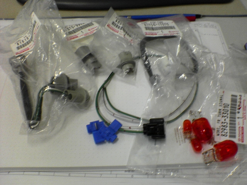
Parts list consits of the following:
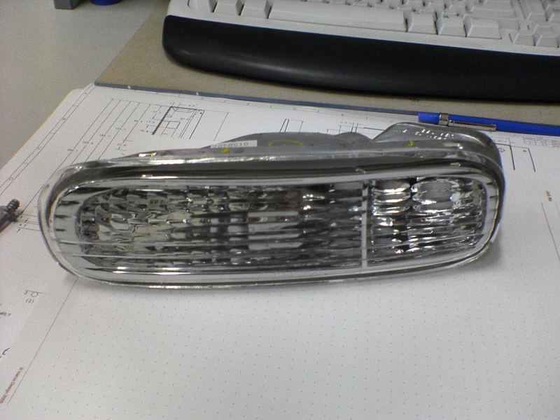
- FL indicator housing
- FR indicator housing
- Socket plug parking light bulb - 90075-60001
- Socket plug for main indicator bulb - 90075 - 99080
- FR Turn signal chord - 81515 - 14390
- FR Turn signal wire - 82983 - 33010
- Side turn chord - 81735 - 17070
- Small Wedge Parker bulbs x 2
- Large Wedge Indicator bulbs x 2
Ill try and explain this as quickly/simply as possible. Its no real brain teaser if you think about what youre doing. Please keep in mind that im not saying that the way i did it is the right way or the only way...i guess it just comes down to whatever works and what youre happy with in the end.
2 things to note...i did absolutely no drilling into my stock front bar...will explain why later on, and i didnt do any modifications to the existing wiring in the supra. All wiring modifications were done to the extra wiring looms that i bought. Basically chose to do most of the job this way so that if i ever choose to go back to original form then i can do so without any problems.
So without further adoooo.....heres the write up...
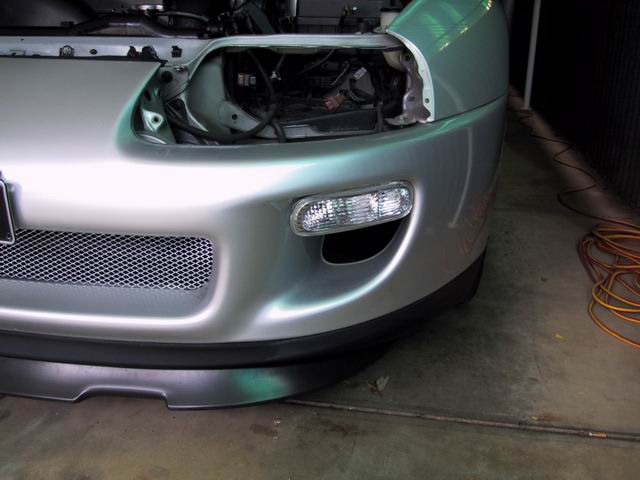
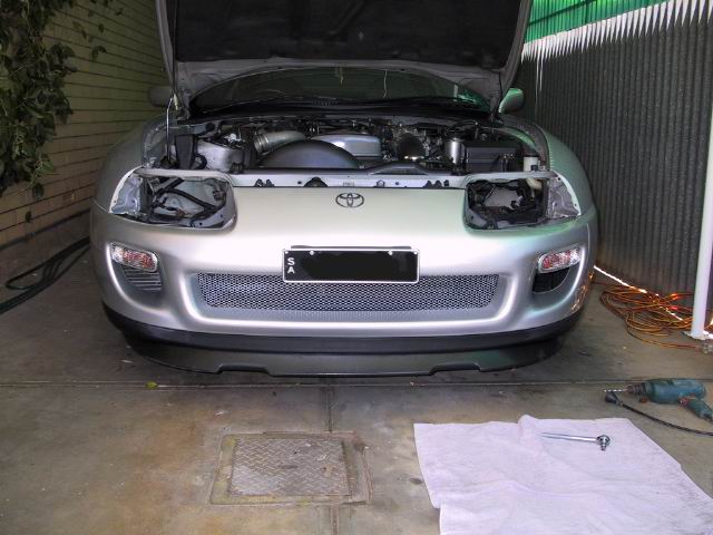
PART 1 (Removing the old indicators)
Started off with essentially pulling out my battery...just to give me some better room to work in...when pulling out my headlight, and then the indicator.
Then on the LHS i decided to pull all of my stock airintake out, so the induction pipes, filter and air box, and front intake. Basically as above just to give me some room to work in when doing the LHS indicator.
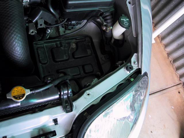
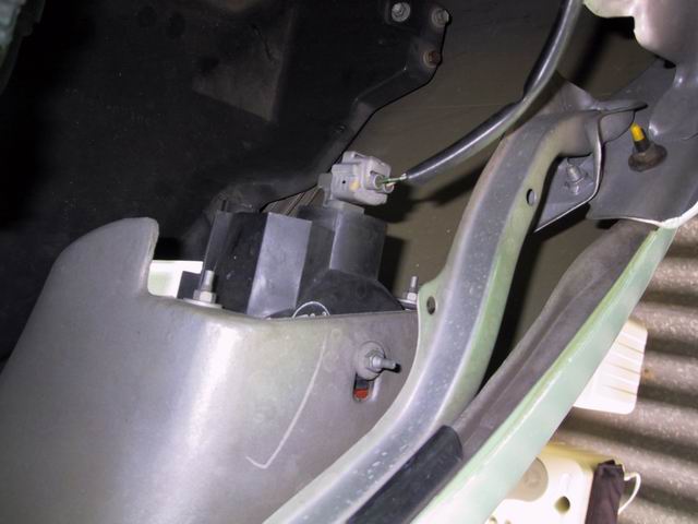
With RHS headlight pull you can now see i have complete access to the indicator and the 3 bolts holding it on to my front bar. these require an 8mm socket to take off or anything suitable for an 8mm head. As for the LHS indicator there is absolutely no chance of using a socket to take the bolts off so other tools were needed.
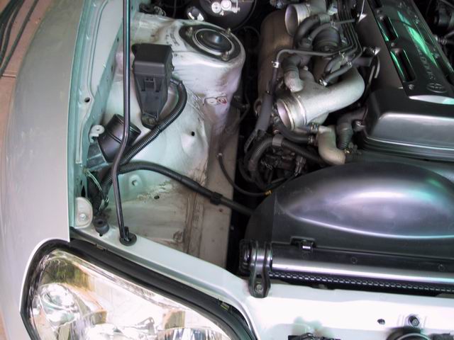
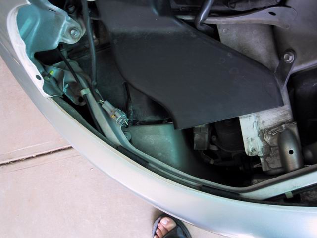
With the LHS headlight pulled you can begin to understand the difficulty that youre going to have when pulling off and putting in the new indicator. The intake panel you can see in the picture was also removed in order to make more room. the LHS indicator also has 3 bolts holding it in, theyre just much more difficult to get to.
This pic just shows the main RHS indicator loom detached from the old bulb socket.
This picture just shows the main LHS indicator loom detached from the old LHS indicator.
If you havent been able to tell yet...there is a difference between the two sides...the RHS indicator only requires you to plug the main loom into a socket sitting in the indicator but the LHS has its own wire loom and a different connector feeding directly out of the bulb socket and connecting the the main LHS wire loom.(again i remind you that i didnt modify any of the existing wiring)
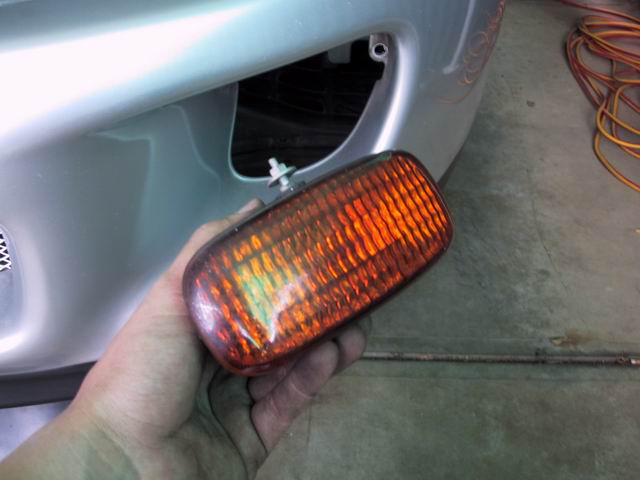
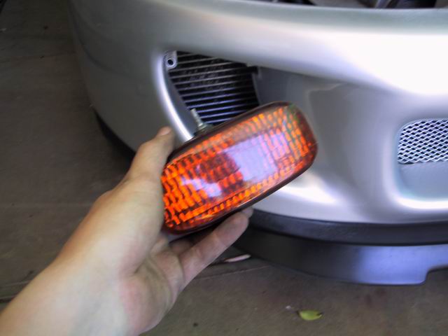
With the 3 bolts undone on the RHS indicator the main indicator pops out with ease...
this pic just shows a test fit of the new indicator...**i should note that the new indicators have a different mounting point. They have the 2 at the rear just like in the old one but instead of having one at the top they have one popping out the side...This is were you can chose to drill a hold for this mount in the side of your front bar or do as i did and remove the insert thread and just use the rear 2 to mount your indicators. When done up tightly enough they sit home pretty well...Ive found that one side sags a little so i plan on using some double sided tape to keep it in position (havent done this yet but either way its unnoticeable)
Now the picture below shows the LHS idicator out but in order to get to that stage, i had to firstly undo the top bolt with an 8mm spanner, then undo the first rear bolt with the same spanner through the top where the headlight used to sit. The last rear bolt was the worst for me and took the longest amount of time...it was rusted and the only way i could get to it was through the front side intake where your stock intercooler sits. Took a while and threw several fits trying to undo it but i got there in the end...
PART 2 (wiring and assembly)
Doing the RHS indicator is extremely easy, given that i had a direct plug in bulb socket for the indicators, its just a matter of sticking the bulbs into the New bulb sockets and popping the sockets into the indicator. Only tricky thing that you might have to do is extend the main wire loom to reach the main indicator bulb socket. You do this by simply removing one of the rubber zip ties at the rear of the wire loom so that it gives you a bit more slack and you can then just plug it into the new bulb socket.
RHS indicator is done...
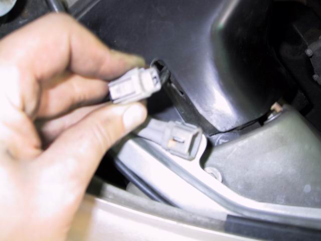
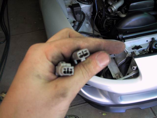
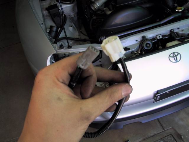
LHS is where the fun is at...the first picture shows the existing wire loom connector (LEFT) and the new connector/wire (RIGHT). The new one being slghtly different requires some modification in order for it to fit the exsiting Main wire connector. To modify it you have the remove a clip from one of its sides (cut it off) and in the head of the connector grab some pliers or similar and remove a little white plastic spacer in the head of the connector. Once this is done it should closely resemble the old connector and you should be able to use it in the Main connector. The Newly modified one wont clip in like the old one but it has a tight enough tollerance so that when you push it home it will sit in there securely. *dont connect anything up yet...you have to do the cutting and splicing first.
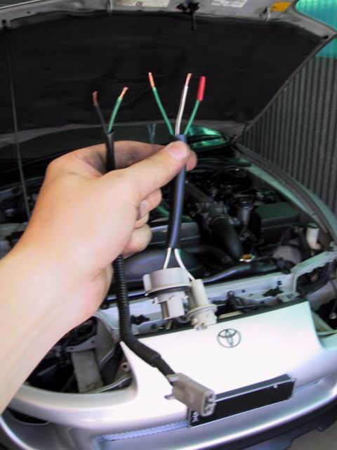
the next photo shows the new wire loom and sockets for the LHS indicator...the sockets are fine as they are but you have to cut off the connector on the other end. This connector is only suitable for the late model main wire and so it wont fit onto any of your existing connectors. The plan here is to basically remove the unusable connector and replace it with the newly modified one that i had created earlier.
this next photo shows the connector the i modifed and the (white) connector that has to be removed in order to splice the modified connector to your bulb socket wires.
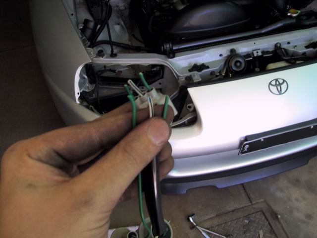
The next picture just shows the connector removed from the blub socket wires...as youll notice there are 3 wires and not 2. there are 2 wires that lead to your main indicator socket and there is one separate one for your parker lights. The separate wire for the parkers is not used in the early model supra as you have your parkers elsewhere. There is probably a way to wire this up so that it works to but at this stage ive simply trimed it and taped it off.
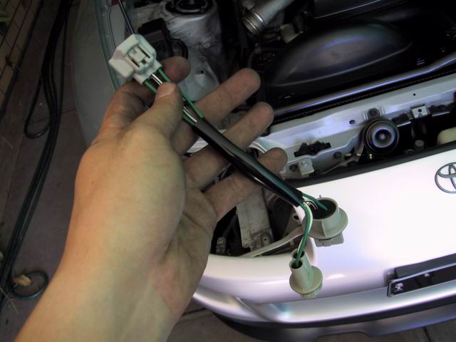
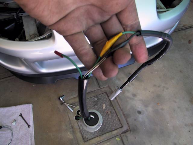
Now this next set of images shows the 2 different wires, the modified connector with 2 wires - GREEN & BLACK (LEFT) and the socket wires with 3 wires - 2 GREEN & 1 WHITE/BLACK (RIGHT). I taped off the unused green wire leading to the parker light just so i would also know that i wouldnt need it. So basically all you need to do is the following:
CONNECT GREEN TO GREEN
CONNECT BLACK TO WHITE/BLACK
And basically the way you do it is you carefully strip the wires till you have about 10mm of wire exposed on each of your ends. And you can either do it properly and solder the ends of the wires together or if you have the tools crimp the wires. But i went for the twist and tape method...so i basically made sure that i securely twisted the wires togther and then using electrical tape, wrapped up the twisted ends so that the wouldnt budge. Will probably do this properly at some stage but while its working fine ill leave it as is....so as i mentioned before...im not claiming this to be the only way or right way to do it. Its just the way i did it and it works!
Essentially once this is done...you plug you bulbs into the new sockets as was done in the RHS. Drop the sockets into the new indicator. Attach the indicator using only the 2 rear screws. Much easier and quicker this time...and then i simply put all the other bits in that where taken out, eg, headlights, induction, battery etc. and thats it...."
Here is a helpfully hint from another guy
I would like to add that on the NA(-T) neither side has bolts that are
difficult to remove to get out the stock turn signals (once the
headlights are removed). As mentioned, the clear turn signals have two
mounting screws that fit nicely into the stock holes but a third one on
the side that can't be used as is. I originally test mounted them with
just the two screws/nuts and the lamps really don't sit up tight into
position - not to my liking anyway. I decided to drill holes for the
third screw and thought I'd share the trick I used to do it.
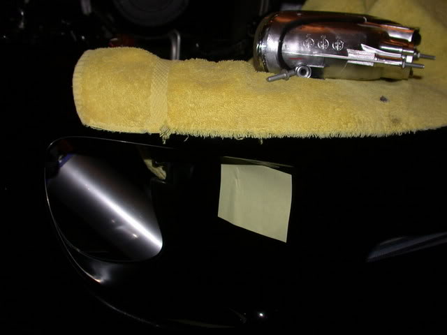
1. Unscrew the side screw from the clear turn signal (you need to do
this whether you decide to drill or not). Place the signal in the two
stock screw holes. Look at the underside of the signal and note
approximately where the hole will need to be drilled. Place a Post-it
note over the area:
Side-screw removed and Post-it in place:
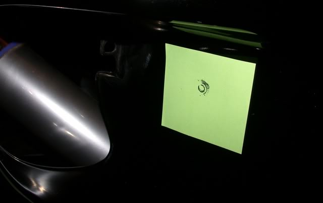
2. Take a magic marker and get the side screw hole on the turn signal
good and wet with ink. Now, quickly and carefully put the signal into
place up and tight so that it sits properly. Press the bumper from the
inside firmly about where the screw hole is. Remove the lamp.
While it may take a try or two, this is what you should get - a bulls eye for drilling:
3. Drill the hole through the Post-it/bumper cover with a 7/32 bit.
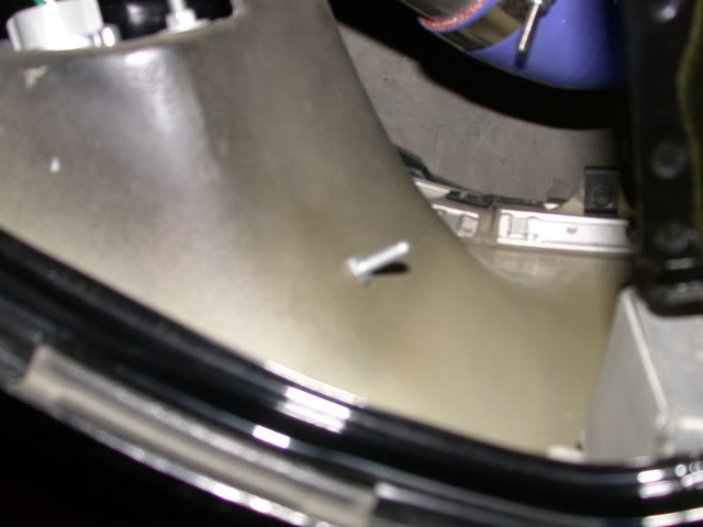
4. Now this is where you might expect to just replace the side screw
and bolt it up. Due to the strange geometry of the three screws, I'm
not sure this is possible - I couldn't get it in this way. What works
great is this; With the side screw out, install the lamp loosely with
the two back screws then screw the side screw in from the inside of the
bumper and tighten it down with a 10mm deep socket.
Sorry a little blurry... the side screw in place: